Main menu
You are here
Object Property View
With the Object Property View you can set all the properties of a 3D object like transformations, materials and textures. You can add shaders to 3D objects. You can add sensors for interactions. In the Object Property View you can also create animations.
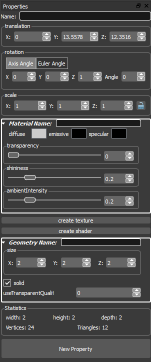
In the first line of property View you can name a object. With this name a object can be accessed from other objects.
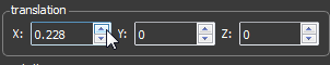
To move the 3D Object you can change the value of one of the three spinboxes. Each spinbox is labled with its associated axis.
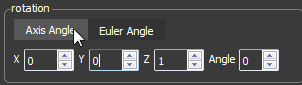
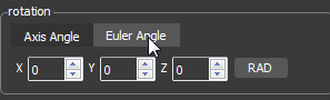
To rotate the 3D Object you can change the value of one of the spinboxes.
Each spinbox is labled with its associated axis. You can switch between
Axis Angle and Euler Angle.
In Axis Angle you rotate around a specified axis. In Euler Angle you can
rotate each axis around specified angle. In Euler Angle you can choose
between radians and degrees.
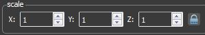
To scale the 3D Object you can change the value of one of the spinboxes. Each spinbox is labled with its associated axis. If the lock button is set all spinboxes are linked and became the same values.
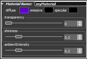
In the material rollout you can define the material name and you can set the diffuse-, emissive- and specular color of a 3D object. With the Transparency Slider or the Transparency Spinbox you can set the transparency of the 3D object. Also you can set the shininess and the ambient intensity.
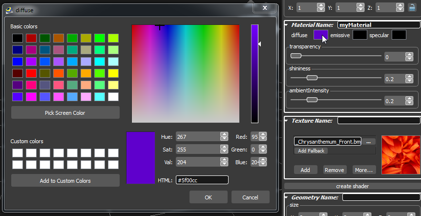
To change the diffuse-, emissive- or specular color click the corresponding color rectangle. In the appearing dialog edit the color.
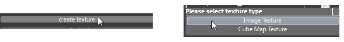
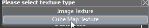
If your 3D object don't have a texture you have to create one. To do so click the create texture button. In the appearing dialog choose Image Texture ore Cube Map Texture.
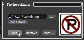
If Image Texture was choosen the texture rollout appears. In the texture rollout you can define the texture name and you can choose a image file.
By clicking the Add Button a multi texture will be created. You can assign a name definition to each single component of multi texture.
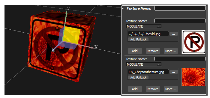
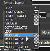
Each component of a multitexture is blended with a blend mode. You can change the blend mode by choosing one out of the blend mode combobox.
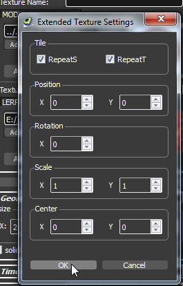
By clicking the More Button the extended texture settings dialog opens. Within this dialog you can set:
- Texture repeat
- Texture position
- Texture rotation
- Texture scale
- Texture center
If you add or create a new texture and choos Cube Map texture a cube map will be added.
In the properties of the cube map six image files for every side of a cube can be defined.
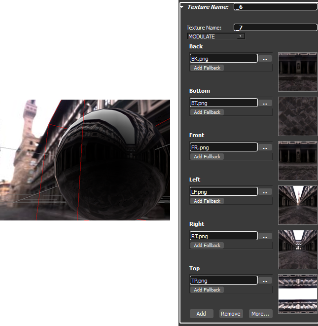
Note that a cube map also requires a shader.
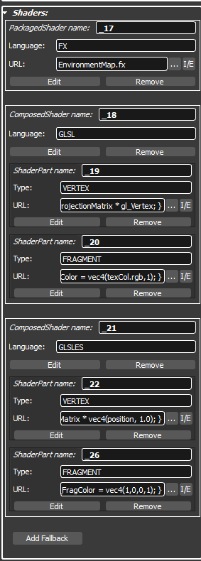
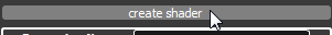
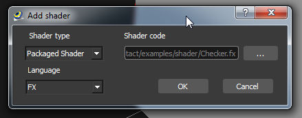
To add a shader to your 3D object, click the create shader button. In the appearing dialog select the Shader type and the Language. Under Shader code select the shader file.
In the shader rollout you can edit, remove and set the shader inline or extern.
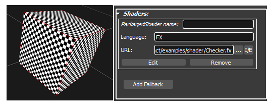
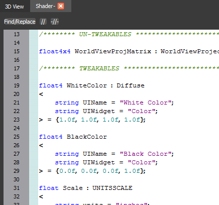
By clicking the Edit Button the shader editor will open.
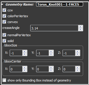
The geometry represents the mesh data of the 3D object. In the geometry rollout you can set the values how the mesh data is rendered and the dimensions of the 3D object. You can define the name of the geometry in the first line of the geometry rollout.
- If ccw is set then mesh´s triangles are rendered counter clockwise. Otherwise the triangles are rendered clockwise.
- If colorPerVertex is set then each vertex can store a color. Otherwise the color is per face
- convex is a hint to triangulate convex 3D objects
- with the creaseAngle you can smoth your 3D object
- If normalPerVertex is set then each vertex holds a normal vector. Otherwise the normal vector is per face
- If solid is set then the 3D object is rendered two sided
- bboxSize sets the size of the bounding box. -1 means automatic calculating at render time.
- bboxCenter sets the pivot of the bounding box.
- If show only Bounding Box instead of geometry is set then you will see a bounding box instead of the mesh
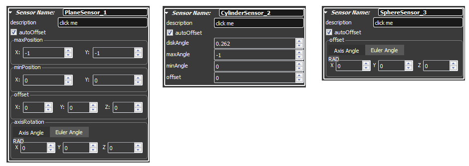
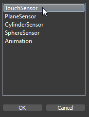
There a different types of GeometrySensors. Geometry sensors are necessary to receive mouse events to interact with the user.
- A TouchSensor receive mouse events if the mouse is over a 3D object.
- With a PlaneSensor you can define a plane in 3D space to receive 2D coordinates according to the defined plane.
- With a CylinderSensor you can define a cylinder in 3D space to receive mouse coordinates that are mapped on the defined cylinder. You can use it to implement a orbiter that works with one axis.
- With a SphereSensor you can define a sphere in 3D space to receive mouse coordinates that are mapped on the defined sphere. You can use it to implement a orbiter that works with two axis.
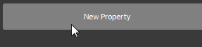
To create a GeometrySensor click the New Property Button and select a GeometrySensor in the appearing dialog.
In the first line you can define a name for the GeometrySensor. Over
this name routes and scripts can communicate with the GeometrySensor.
The value of the field description will
be shown as a tool tip if the mouse is over the 3D object.
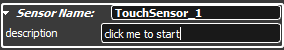
A TouchSensor is the simplest GeometrySensor. PlaneSensor, CylinderSensor and SphereSensor are similar but they have attidional fields to describe their geometry.